Installation Instructions
Caution! Turn off the main power to the circuit before wiring FireAll™
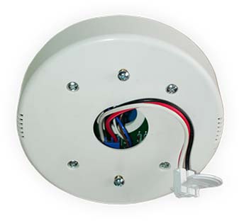
- After removing FireAll™ from the box remove the 4 screws on top that secure the housing to the mounting base and circuit board. When separating the housing from mounting base pay attention to the power led on the side of the housing and realign it using the notch in the housing when reinstalling.
- Locate a 120v ceiling box that is not on a switched circuit or install a new receptacle box and connect it to the power source of the home.
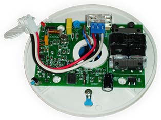
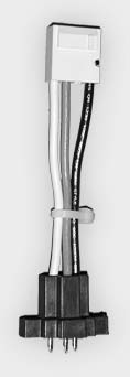
- Take the wire harness that comes with the 120V hardwired smoke alarm and attach it to the FireAll™ circuit board using the terminal block R B W (Red, Black & White).
- There are 3 leads from the circuit board Red, White and Black put them through the back of the mounting base and attach them to the house wiring.
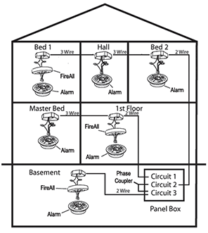
Ex. second floor bedrooms were wired together using the accessibility of the attic (as the image shows) However now you want to interconnect the group with the basement smoke alarm. The FireAll only needs to be installed with one of the group for the whole 2nd floor to be interconnected with the basement.
For alarms that are used as single station with no Red wire in the electric box, DO NOT CONNECT THE RED WIRE OF THE FIREALL TO ANYTHING. Leave the red wire insulating cap in place to make certain that it cannot contact any metal parts or the electrical box.
- Secure the mounting base to the electric box with the two screws on the box.
- Install the housing making certain to line up the hole in the housing with the circuit board power light, there is a notch for the alignment of the housing and mounting base. Install 4 screws.
Now refer to the manufacturers Instructions / User’s Guide for installing and replacing their smoke alarm which will include but not limited to:
- Attach mounting base of smoke alarm to FireAll™ using screws (2) provided with the FireAll
- Plug the harness into the Smoke Alarm and twist lock Alarm into base
Turn on the AC power. The Red Power On Indicator should be lit when the
FireAll™ is connected to the home AC power.. NOW TEST...
Installation Video
Show/hide the video
TESTING THE FIREALL™ SYSTEM
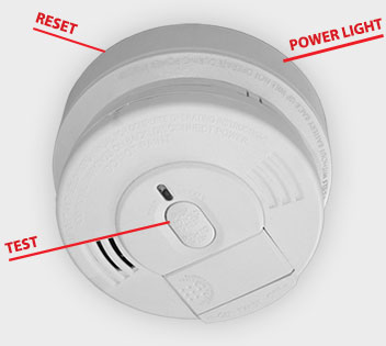
To test that the FireAll™ is interconnected with other units in the home simply push the test button on the smoke alarm. Hold it for the 3rd cycle of beeps, the FireAll™ will receive the signal from the smoke alarm and transmit a 455khz signal on the house wires other FireAlls in the house will receive the signal and sound the alarms attached to it.
TROUBLESHOOTING
If FireAll™ does not interconnect with other FireAll™ s
FIRST TRY THE RESET BUTTON:
Using a paperclip or similar size wire insert it in the small hole on the side of the FireAll™ and press it once, within 1/8” you should feel and hear the click. DO NOT mistake the reset hole for the larger power light hole.
IF IT STILL DOES NOT COMMUNICATE:
Most houses are fed from a 220 volt service which is then split into two phases of 110 volts each in the circuit breaker panel (“breaker box”). The RF signals which are impressed onto the house wiring on one phase, may not travel across to the other phase through the breaker panel. If however, the data transmission is not making it from one phase of house wiring to the other, you may couple the signal between them by having a qualified electrician install a 0.1 microfarad, 240V AC capacitor across your 220 volt line from hot to hot, i.e. across any 220 volt breaker. Or, you can install a phase coupler (or phase bridge). Alternately, you may just solve the problem by simply moving the circuits with the FireAlls to the same phase in the panel box.
FALSE ALARMS
There are only Two Reasons for False Alarms. One could be the smoke alarm that was attached to the FireAll is malfunctioning or needs replacing. FIREALL™ IS NOT A SMOKE ALARM. The FireAll™ is only a transciever that takes a signal from the smoke alarm and communicates it to another FireAll™. Refer to the Smoke Alarm’s User Manual. The other reason could be the FireAll™. In developing the FireAll™ system we set out to achieve three priorities...
- To impress onto the home power lines the strongest signal possible to guarantee its delivery throughout the house,
- Using the best technology available to process and isolate all other RF signals on the power line preventing all potential false alarms.
- It must NOT have the potential to adversely affect the operation of any device attached to it.
FireAll™ will interconnect all FireAlls in a building that share a common service line with a multiple meter pan such as Townhouses. As far as the signal traveling to the street and back to your neighbors FireAll™ our field tests have not shown that to work. However it is mathematically possible. If you know this is the case contact customer support for return information.
REPLACING A SMOKE ALARM OF A DIFFERENT MANUFACTURER
WARNING: DO NOT USE THE TWO PLUG ADAPTER
Sometimes the manufacture provides a two plug adapter with a new smoke alarm for convenience of install, it may damage the FireAll™ when trying to force it in.
- Turn Off power.
- Twist to unlock Alarm from Alarm base and unplug.
- Remove old smoke alarm base.
- Remove 4 screws from housing of FireAll™.
- Take the new alarm harness and replace it with the old one using the blue terminals on the FireAll™ circuit board.
- Using 4 screws reinstall the housing putting the new harness through the center hole.
- Install new smoke alarm base plate.
- Plug in the new alarm curl the harness into FireAll™ and twist onto the base.